- Employ PID control
- Perform linear extrapolation
Objectives
Lab 5 Tasks
- Range/Sampling time discussion
- PID Discussion
- Reaching goal
- Wind-up implementation (5000 level)
Prelab
To have the Artemis communicate with the computer I made two Artemis cases: CHANGE_PID_GAINS and WALL_PID:
   case CHANGE_PID_GAINS:

            // Extract the Kp value from the command string as a float
            success = robot_cmd.get_next_value(Kp);
            if (!success)
                return;

            // Extract the Ki value from the command string as a float
            success = robot_cmd.get_next_value(Ki);
            if (!success)
                return;

            // Extract the Kd value from the command string as a float
            success = robot_cmd.get_next_value(Kd);
            if (!success)
                return;
    break;
case WALL_PID:
        goal_pos = 304; // in mm
        curr_pos = 304; // so that the error is 0 originally
        PWM = 0;
        drive_start = millis();
        PID_prev_time=0;
        error_prev = 0;

        distanceSensor0.setDistanceModeLong();   // distanceSensor0 --> front sensor
        distanceSensor0.setTimingBudgetInMs(33);
        distanceSensor0.setIntermeasurementPeriod(35);

        PID_wall_active = !PID_wall_active;
        if(PID_wall_active == false){stopCar(PWM);}
        PID_counter = 0;

        break;
The first one simply changes the different PID gains, while the second one toggles the flag variable of the PID control for the specified distance of 304mm from the front ToF sensor. For the purposes of testing, PID_wall is toggled off 5 seconds after it was toggled on.
Originally I set up a full PID controller (hence all three weights), but after testing, I decided I would only be keeping PI control because it gets the job done fine even without the D term, which introduces a lot of jerkiness and requires extra memory and computational cost that I don't want my robot to have to expend in the next labs.
This happens inside of the main loop fo the Artemis where the following code is executed so long as the PID_wall_active flag is set to true:
if(PID_wall_active==true){
                PID_time = millis();
                if(PID_time-drive_start > 5000){PID_wall_active=false;stopCar(PWM);error_i = 0;
                for(int i=0;i < PID_counter; i++){
                         tx_estring_value.clear();
                         tx_estring_value.append("T:");
                         tx_estring_value.append(timestamps[i]);
                         tx_estring_value.append(",P:");
                         tx_estring_value.append(errors_P[i]);
                         tx_estring_value.append(",I:");
                         tx_estring_value.append(errors_I[i]);
                         tx_estring_value.append(",A:");
                         tx_estring_value.append(ToFs0[i]);
                         tx_estring_value.append(",S:");
                         tx_estring_value.append(PWMs[i]);
                         tx_characteristic_string.writeValue(tx_estring_value.c_str());
                                            }
                continue;
                }
                curr_pos = ToFmeasurement(); // now the error is no longer 0
                ToFs0[PID_counter] = curr_pos;
                error_p = curr_pos - goal_pos;
                error_i += error_p;//*(PID_time-PID_prev_time)/1000;
                errors_P[PID_counter] = error_p;
                errors_I[PID_counter] = error_i;
                timestamps[PID_counter] = PID_time;
                    if(error_p > 10 || error_p < -10 ){
                    PWM = Kp * (curr_pos - goal_pos) + Ki * error_i;// + Kd * error_d;
                    if(PWM > 0){PWM+=30;}
                    else if(PWM < 0){PWM-=35;}
                    // added min value for PWM so that it gets out of the deadband zone
                    PWM = constrain(PWM, -255, 255); // so it doesn't overcome 255
                    moveCar(PWM);
                    PWMs[PID_counter]=PWM;
                }
                else{
                    error_i = 0; // ==> I have set it up so that error_i is zeroed when we reach our goal
                    PWMs[PID_counter]=0;
                }
            PID_counter +=1;
            PID_prev_time = PID_time;
            }
Based on the PI controller, a PWM is sent to the car with the moveCar function which makes the car go forward or backward based on the sign of PWM which can be negative or positive.
All of the measurements taken during those 5s are saved in their respective arrays and are sent to the computer at the end, where it is handled by the following function:
def PID_handler(uuid, byteArray):
    string = ble.bytearray_to_string(byteArray).strip()
    T,P,I,A,S = string.split(",")
    time = float(T[2:])
    error_p = float(P[2:])
    error_i = float(I[2:])
    distance0= float(A[2:])
    speed = float(S[2:])
    Timestamps.append(time)
    P_errors.append(error_p)
    I_errors.append(error_i)
    ToFs0.append(distance0)
    speeds.append(speed)
    goal_pos.append(304)
The PI's workflow is the following:
- ToF measurement
- calculation of proportional error term
- calculation of integral error term
- based on gains, PWM is determined and sent to car
Range/Sampling time discussion
In the code above, and more specifically the three lines:
distanceSensor0.setDistanceModeLong(); // distanceSensor0 --> front sensor
distanceSensor0.setTimingBudgetInMs(33);
distanceSensor0.setIntermeasurementPeriod(35);
I set the ToF to long mode, I set the timing budget to 33ms and the intermeasurement period to 35ms.
This results in lost accuracy but, in return, we have faster updates. The point of this class is for our robot to be... fast. For this to be the case, the robot needs to be able to get measurements fast in order to avoid obstacles when moving in high speed.
Additionally, our robots are not accurate either way- there is a lot of noise present no matter how accurate our measuremetns. For this reason, I opted to trade of the accuracy for the sampling speed.
PID Discussion
Proportional Part
I am going to be placing my robot approximately 3m away from a wall. The goal is 304mm. This means that the approximate max error will be 3000-300 = 2700. To calculate a Kp value that will keep us in a max of 100 PWM, we solve: PWM=K_p*e_p and we get ~0.037
Since I have added if(PWM > 0){PWM+=30;} and else if(PWM < 0 ){PWM-=35;}, when PWM is 100, it will be turned into 133, and when it is 3, it will be 33 which is the speed at which my car can move. Same for backwards with the respective number to escape the deadband range. To make sure my car would not try to send a higher than 255 PWM signal I added PWM = constrain(PWM, -255, 255);.
Also, as is shown in the code in the prelab section, I made it so that the integral term is zeroed when the robot reached the goal and stabilized, to prevent overshooting as much as possible in the perturbations (this can be seen in plot 4). For the pertrubations, to save battery, I have also made the robot turn off the motors completely when it reaches the goal and stabilizes.
(Note: due to the space I was in on Monday, I had to do the tests from 2m. The first two plots are slightly below that. Due to lack of time, I had to keep going with those.)
Video 1: Kp = 0.037
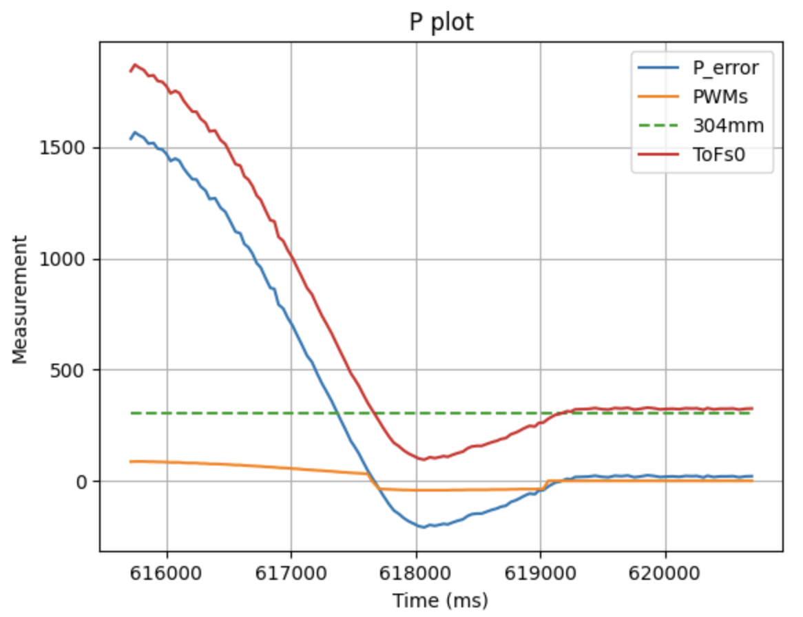
Plot 1: P control, Kp = 0.037
I tested with a Kp of 0.047, but it was worse in terms of only P control. I will add an I term either way so I stuck with 0.037. Below we can see the results of the test with Kp = 0.047
Video 2: Kp = 0.047
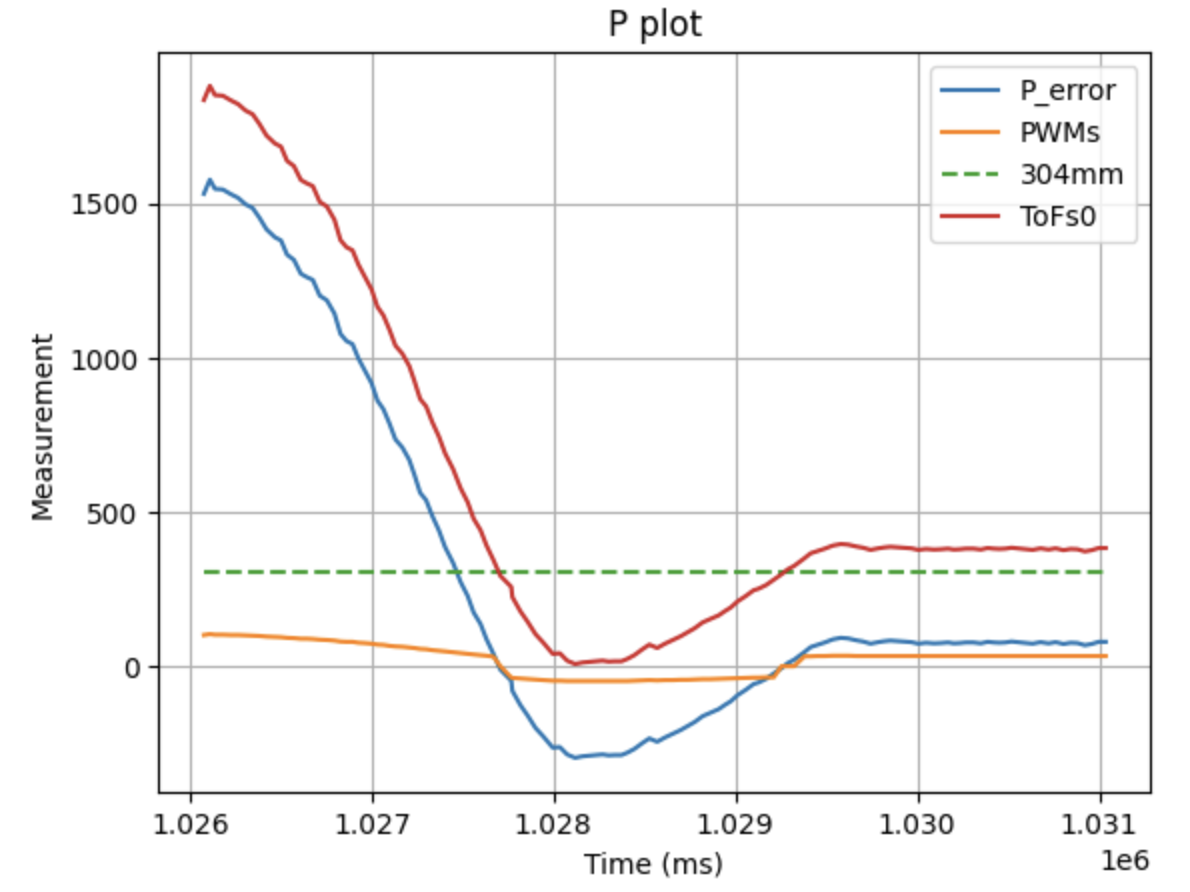
Plot 2: P control, Kp = 0.047
Integral Part
Proportional control on its own, was either too slow (for my taste, and the purposes of the class), or too fast. One thing that can solve this is keeping the slower version of P control (smaller Kp gain) and adding the I term as was shown in prelab section. To avoid overshooting and achieve stabilization, as I mentioned, the integral part of the error is zeroed when the robot reaches the goal. The logic behind this is that if the robot surpasses the goal due to momentum, the integral and the proportional terms will both be negative, "pulling" the robot back to the goal position.
To tune the I term, I originally used Kp = 0.037 and Ki = 0.001 and after testing I ended up with Kp = 0.035, Ki=0.001:
Video 3: Kp = 0.037 Ki = 0.001
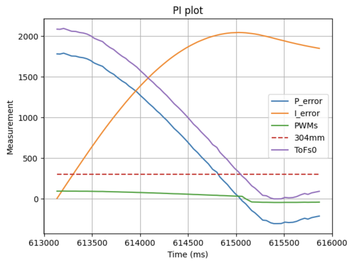
Plot 3: PI control, Kp = 0.035, Ki = 0.001
Video 4: Kp = 0.035 Ki = 0.001
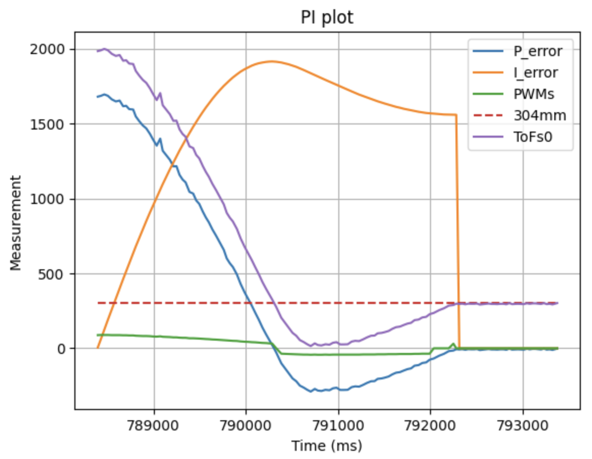
Plot 4: PI control, Kp = 0.035, Ki = 0.001
(Above, we can see the zeroing of the Integral error here that was described above.
Reaching goal and Perturbations
In the following video, we can see the car reaching the goal and reacting to perturbations. As I want the robot to be able to react at all times, I have disabled the 5s limit and the debugging data sending to the computer so that it can run indefinetely.
Video 5: Reaching Goal and Reacting to Perturbations
Extrapolation
Through the timestamps array, I saw that the ToF was collecting data once every: ~33-40 milliseconds on average.
On the other hand, the PI loop (having commented out curr_pos = ToFmeasurement(); and added a Serial.println(PID_time - PID_prev_time); at the very end of my loop) ran once every: 20 milliseconds.
To calculate the PI control every loop, I changed it so that it didn't wait for ToF measurements. If a measurement was not ready, extrapolation happened.
This was achieved by adding distanceSensor0.startRanging(); in the WALL_PID case and having the following in the final loop (along with other tweaks):
if(distanceSensor0.checkForDataReady())
    {curr_pos = distanceSensor0.getDistance();ToFtimestamps[tofcounter] = PID_time;ToFs0[tofcounter] = curr_pos;tofcounter+=1;
        distanceSensor0.clearInterrupt();}
else if(tofcounter>1)
        {slope = (ToFs0[tofcounter-1]-ToFs0[tofcounter-2])/(ToFtimestamps[tofcounter-1]-ToFtimestamps[tofcounter-2]);
        curr_pos = ToFs0[tofcounter-1]+ (slope*(millis()-ToFtimestamps[tofcounter-1])/1000.0);
        timestamps[extrapolationcounter]=millis();
        ToFs[extrapolationcounter]=curr_pos;extrapolationcounter+=1;
        }
Video 6: Robot reaching goal with raw and extrapolated data
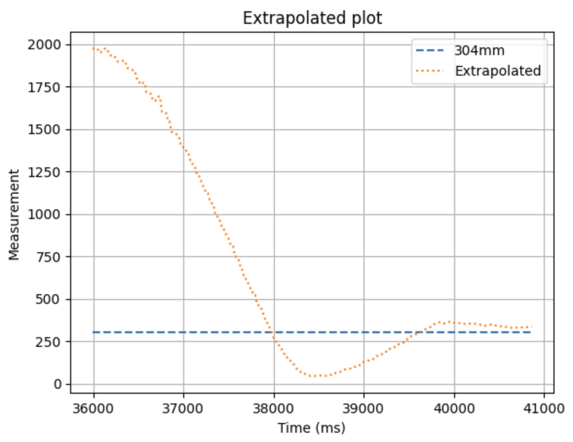
Plot 5: Extrapolated data from ToF
Though not super evident from the video, we can observe that, using extrapolation, the car is deaccelerating faster after passing the goal position This is because of the higher sampling rate than having just the ToF readings. This can be observed by comparing Plot 5 with Plot 4, where the ToF readings are closer to 0 than the extrapolated ones. This allows for our robot to be... Fast, while maintaining better control compared to only ToF.
Wind-up implementation
I first thought of how important this section is when trying to showcase my robot to a friend on the carpet floor of the design complex at Tang Hall. The carpet made the car accumulate so much error before it can start moving, that it made it ZOOM into the wall.
Video 7: Robot without wind-up protection.
In order to overcome this issue, I simply made it so that, once the I term has exceeded 1000, or went below -1000, it stayed at the respective value.
I selected that value due to the plots I got from my PI control testing. If i was at 4 meters and not 2, having that high an integral term would have been bad.
This was achieved with the following code:
error_i += error_p*(PID_time-PID_prev_time)/1000;
    if(error_i>1000){error_i=1000;}
    else if(error_i<-1000){error_i=-1000;}
Now we can see the result where the windup isn't disastrous:
Video 8: Robot with wind-up protection.
Discussion
I finished this lab at 3:40 am on Tuesday morning, which is absolutely unusual for me. This happened due to my robot's left motor driver breaking on Saturday. I had to wait until today in the evening to get a replacement. I sincerely apologize if this report is not typed up to the usual standards.
Lab 5 successfully employed PI control for the car as well as linear extrapolation of data points of the ToF sensor.
Collaboration
I used Kimi for debugging and referred to Lucca Correia's website for structuring this lab report.