- Utilize IMU to obtain z-axis rotation (yaw)
- Employ angular PID control
Objectives
Lab 6 Tasks
- Range/Sampling time discussion
- PID Discussion
- Reaching goal
- Wind-up implementation (5000 level)
Prelab
To have the Artemis communicate with the computer I made two additional Artemis cases similar to the ones from Lab5: CHANGE_PID_ROT_GAINS and ROT_PID:
   case CHANGE_PID_ROT_GAINS:

            // Extract the Kp value from the command string as a float
            success = robot_cmd.get_next_value(Kp_rot);
            if (!success)
                return;

            // Extract the Ki value from the command string as a float
            success = robot_cmd.get_next_value(Ki_rot);
            if (!success)
                return;

            // Extract the Kd value from the command string as a float
            success = robot_cmd.get_next_value(Kd_rot);
            if (!success)
                return;
    break;
After determining I will not be using the Derivative term in my controler, I changed the code above, so that the third float changes the goal angle of the control with the following line success = robot_cmd.get_next_value(goal_angle);
case ROT_PID:
        goal_angle = 0; // in degrees
        curr_angle = 0; // so that the error is 0 originally
        PWM_rot = 0;
        drive_start_rot = millis();
        PID_prev_time_rot=drive_start_rot;
        error_prev_rot = 0;
        error_i_rot = 0;

        dT_rot=0;
        T0_rot=micros();
        Now_rot=0;
        myICM.resetFIFO();


        PID_rotation_active = !PID_rotation_active;

        if(PID_rotation_active == false){stopCarRotation();}
        PID_counter_rot = 0;
        calc_yaw = 0.0;

break;
The first one changes the different PID gains for the rotational control. The second one toggles the flag variable of the rotational PID control. For the purposes of testing, PID_rotation is toggled off 5 seconds after it was toggled on.
Despite setting up a full PID controller (hence all three weights), just like the previous lab, I decided I would only be keeping PI control because it gets the job done fine even without the D term, which requires extra memory and computational cost that I don't want my robot to have.
The orientation control happens inside of the main loop of the Artemis where the following code is executed so long as the PID_rotation_active flag is set to true:
if(PID_rotation_active==true){

            PID_time_rot = millis();
            if(PID_time_rot-drive_start_rot > 5000){PID_rotation_active=false;stopCarRotation();error_i_rot = 0;
            for(int i=0;i < PID_counter_rot;i++){

            tx_estring_value.clear();
            tx_estring_value.append("T:");
            tx_estring_value.append(timestamps[i]);
            tx_estring_value.append(",P:");
            tx_estring_value.append(errors_P[i]);
            tx_estring_value.append(",I:");
            tx_estring_value.append(errors_I[i]);
            //tx_estring_value.append(",D:");
            //tx_estring_value.append(errors_D[i]);
            tx_estring_value.append(",Y:");
            tx_estring_value.append(yaws[i]);
            tx_estring_value.append(",S:");
            tx_estring_value.append(PWMs[i]);
            tx_characteristic_string.writeValue(tx_estring_value.c_str());
                                            }
            continue;
            }
            dmp_yaw = getDMPyaw();
            yaws[PID_counter_rot] = dmp_yaw;
            curr_angle=dmp_yaw;
            error_p_rot = curr_angle - goal_angle;
            reciprocal_angle = goal_angle - (goal_angle < 0 ? -1 : 1) * 180;
            if (abs(error_p_rot) > 180.0) {error_p_rot += (reciprocal_angle - curr_angle) / abs(reciprocal_angle - curr_angle) * 360.0;}
            error_i_rot += error_p_rot*(PID_time_rot-PID_prev_time_rot)/1000;
            //error_d_rot = (float(error_p_rot) - float(error_prev_rot))/(float(PID_time_rot) - float(PID_prev_time_rot));
            timestamps[PID_counter_rot] = PID_time_rot;
            errors_P[PID_counter_rot] = error_p_rot;
            errors_I[PID_counter_rot] = error_i_rot;
            //errors_D[PID_counter_rot] = error_d_rot;


            PWM_rot = Kp_rot * error_p_rot + Ki_rot * error_i_rot;// + Kd_rot * error_d_rot;
            if(PWM_rot>0){PWM_rot+=155;}
            else if(PWM_rot < 0){PWM_rot-=155;}
            // add min value for PWM so that it moves
            PWM_rot = constrain(PWM_rot, -255, 255);
            rotateCar(PWM_rot);
            PWMs[PID_counter_rot]=PWM_rot;

            PID_counter_rot +=1;
            PID_prev_time_rot = PID_time_rot;
            //error_prev_rot = error_p_rot;
}
Based on the PI controller, a PWM is sent to the car with the rotateCar function which makes the car rotate clockwise or counterclockwise based on the sign of PWM which can be positive or negative respectively.
All of the measurements taken during those 5s are saved in their respective arrays and are sent to the computer at the end, where it is handled by the following handler:
def PID_ROT_handler(uuid, byteArray):
    string = ble.bytearray_to_string(byteArray).strip()
    T,P,I,Y,S = string.split(",")
    time = float(T[2:])
    error_p = float(P[2:])
    error_i = float(I[2:])
    #error_d = float(D[2:])
    yaw= float(Y[2:])
    speed = float(S[2:])
    Timestamps.append(time)
    P_errors.append(error_p)
    I_errors.append(error_i)
    #D_errors.append(error_d)
    yaws.append(yaw)
    speeds.append(speed)
    goal_angles.append(0)
The PI's workflow is the following:
- theta (yaw) is calculated from IMU's dmp
- calculation of proportional error term
- calculation of integral error term
- based on gains, PWM is determined and sent to car
getDMPyaw function returns the theta and is described here:
float getDMPyaw() {

    icm_20948_DMP_data_t dmp;
  do {
    myICM.readDMPdataFromFIFO(&dmp);
  } while (myICM.status == ICM_20948_Stat_FIFOMoreDataAvail);

  if (myICM.status == ICM_20948_Stat_Ok) {
    if ((dmp.header & DMP_header_bitmap_Quat6) > 0) {

      float qx = ((double)dmp.Quat6.Data.Q1) / 1073741824.0;
      float qy = ((double)dmp.Quat6.Data.Q2) / 1073741824.0;  // takes scale to [-1,+1]
      float qz = ((double)dmp.Quat6.Data.Q3) / 1073741824.0;

      // Quaternion to Euler angle conversion
      float qw = sqrt(1.0 - min(((qx * qx) + (qy * qy) + (qz * qz)), 1.0));

      // Yaw (z-axis rotation)
      float siny = 2.0 * (qw * qz + qx * qy);
      float cosy = 1.0 - 2.0 * (qy * qy + qz * qz);
      float yaw_dmp = (float)(atan2(siny, cosy) * 180.0 / PI);

      calc_yaw = yaw_dmp;
      return calc_yaw;
    }
  }
  return calc_yaw; // returns the old one if a new one isn't ready!
}
Range/Sampling time discussion
In the code above, and more specifically in:
myICM.readDMPdataFromFIFO(&dmp);
The data is read from the First-In-First-Out (FIFO) buffer which "fill up" at a rate of 1.125kHz which is extremely fast for our purposes. This would mean that the buffer could consume all the memory of my Artemis and make it crash. However, with the following line in setup:
myICM.setDMPODRrate(DMP_ODR_Reg_Quat6, 1.5);
that can be divided by three and be equal to 750Hz, which is a pretty good sampling time for us, and the sweet spot between memory usage and frequency of samplings. (I tested dividing by 3 and 2 but the signals weren't as smooth)
PID Discussion
As said in the prelab section, only PI is going to be used for the reasons mentioned there.
Proportional Part
Like in previous Lab, I have set it so that the deadband PWM value for rotation is added to whatever the contorller outputs. So, for the max PWM value of 255, I want the controller to output 90, as I have added 155 to it (or subtracted when it's negative). I am not adding 165 to have some slack. To calculate a Kp value that will keep us in a max output of 90 PWM, we solve: PWM=K_p*e_p for the max e_p being 180, and we get K_p=0.5
I have added if(PWM > 0){PWM+=155;} and else if(PWM < 0 ){PWM-=155;}, when PWM is 90, it will be turned into 245, and when it is 0, it will be 155 which is right under the speed at which my car can rotate. To make sure my car would not try to send a higher than 255 PWM signal I added PWM = constrain(PWM, -255, 255);.
Video 1: Kp_rot = 0.5
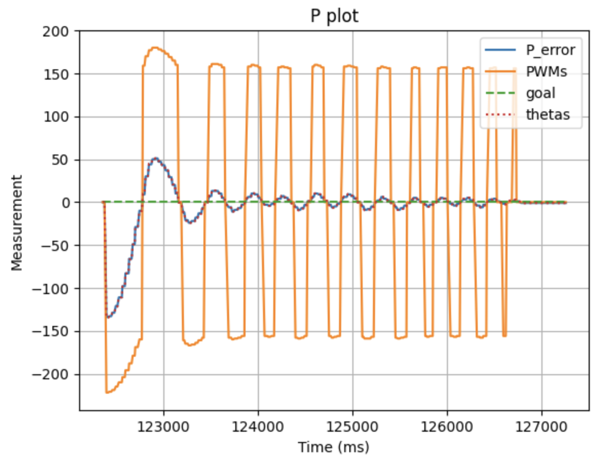
Plot 1: P control, Kp_rot = 0.5
We can observe intense oscillations. The Kp is too high.
To test further I wanted to include the I term.
Integral Part
I started off with a tiny Kp value of 0.05 and a Ki value of 0.01:
Video 2: Kp = 0.037 Ki = 0.001
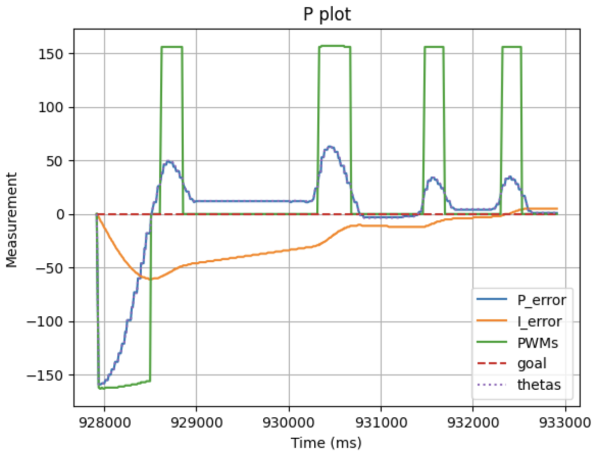
Plot 2: PI control, Kp = 0.035, Ki = 0.001
In the video above, we saw how Zeus (the robot) is capable of reacting to perturbations. The zeroing of the PWM values might seem strange originally but there is an explanation:
> from 929k to 930k, the negative I term opposes the current P term. Afterwards, the P and I terms are so close to zero that the PWM (being an int variable) is rounded to 0.
>> To fix this, I tuned both gains as the accumulated 'I' term would oppose the 'P' term's opposite sign oscillations.
After some tuning, I ended up with Kp = 0.057 and Ki = 0.092. The robot correctly stops at 0, and the oscillation to get there is pretty minimal.
Video 3: Kp = 0.057 Ki = 0.092
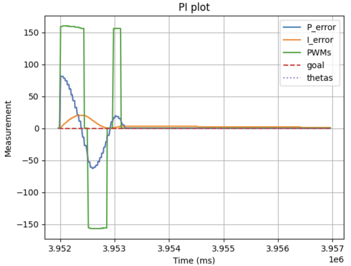
Plot 3: PI control, Kp = 0.057, Ki = 0.092
After some more tuning, I ended up with Kp = 0.045 and Ki = 0.052. The robot stops almost at 0, an 'almost' that we can tolerate as our system isn't accurate at all either way, and the oscillation to get there is pretty minimal even at almost -150 degrees initial error. Especially given the fact that I'll employ extra tactics in the future labs to ensure stability.
Video 4: Kp = 0.045 Ki = 0.052
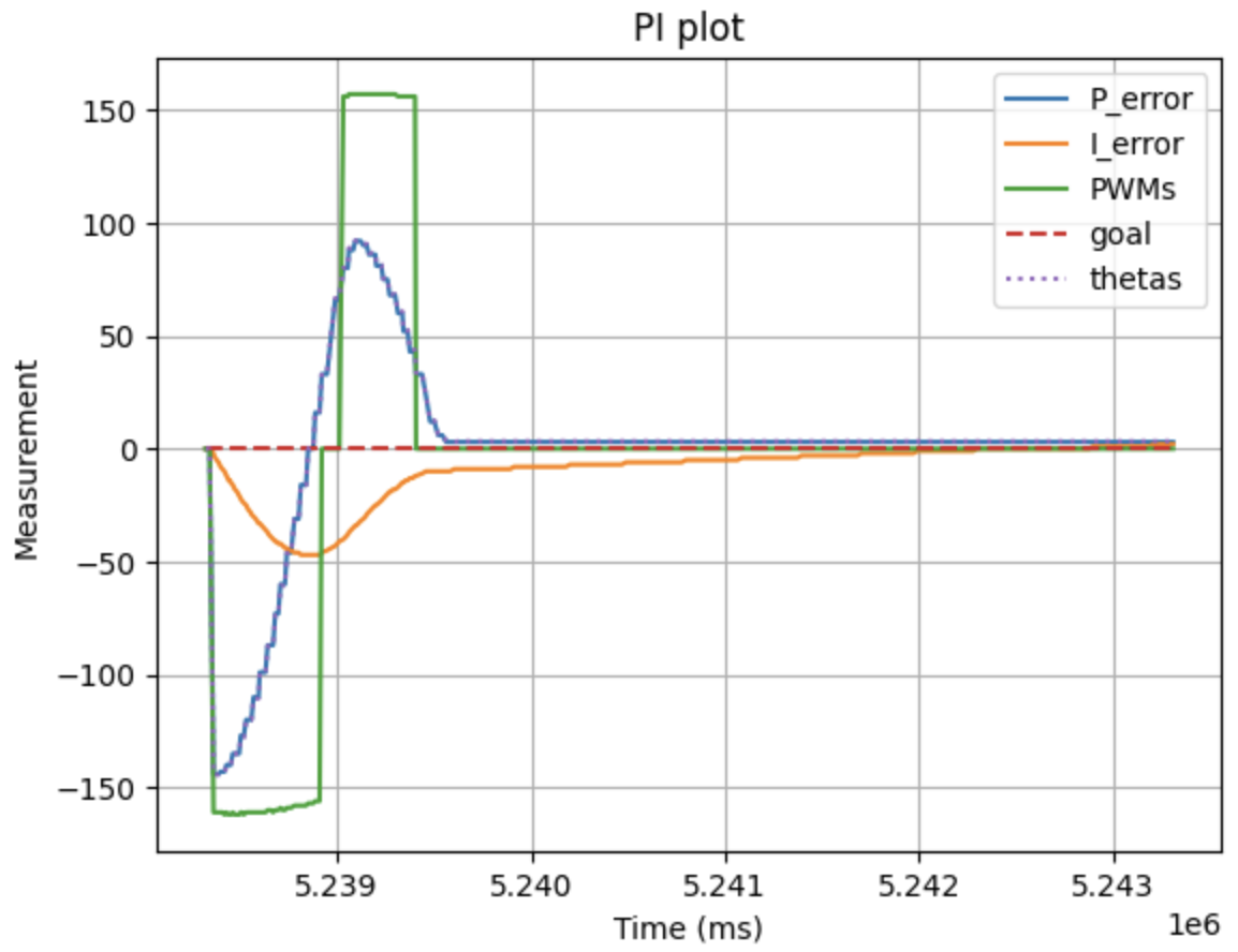
Plot 4: PI control, Kp = 0.045, Ki = 0.052
Reaching goal and Perturbations
In the following video, we can see the car reaching the goal and reacting to perturbations. As I want the robot to be able to react at all times, I have disabled the 5s limit and the debugging data sending to the computer so that it can run indefinetely.
Video 5: Reaching Goal and Reacting to Perturbations
Wind-up implementation
As we can see from the following video, the wind-up protection is extremely important as in that case, the car completely loses the ability to stabilize.
Video 6: Robot without wind-up protection.
In order to overcome this issue, I simply made it so that, once the I term has exceeded 35, or went below -35, it stayed at the respective value.
I selected that value based on to the plots I got from my PI control testing.
This was achieved with the following code:
error_i_rot += error_p_rot*(PID_time_rot-PID_prev_time_rot)/1000;
    if(error_i_rot>35){error_i_rot=35;}
    else if(error_i_rot<-35){error_i_rot=-35;}
Now we can see the result where the windup isn't disastrous:
Video 7: Robot with wind-up protection.
Discussion
Lab 6 successfully employed rotational PI control for the car by utilizing the IMU's Digital Motion Processor.
Collaboration
I used Claude for debugging and referred to Lucca Correia's website for structuring this lab report.